
A workable palm oil equipment layout must show more than where each machine stands. It needs to demonstrate how material passes between stations, where utilities connect, how people reach operating and maintenance points, and how large components can be removed. Check those interfaces before approving the arrangement drawing, while changes are still easier to coordinate.
This review begins after the basic process and site have been chosen. It complements site-selection planning but answers a different question: can the proposed equipment be installed, connected, operated, and maintained within the available space? The following method creates a practical record for the buyer, supplier, and installation team.
Use One Drawing Reference System
Start with a site plan that identifies fixed structures and a common reference for dimensions and elevations. Include existing foundations, columns, doors, roads, drains, and utility routes that affect the installation. A simple sketch is useful at an early stage, but dimensions that will control fabrication need verification.
Keep the equipment arrangement, civil drawings, and piping information on compatible references. If different contractors use different elevation origins, a connection can appear correct on each drawing while failing to meet on site. State the reference and units on the documents exchanged for review.
For a retrofit, measure the existing installation rather than assuming old drawings represent its current condition. Record where access prevented a reliable measurement. Treat those locations as open verification items before ordering equipment that depends on them.
Follow the Material from Reception to Its Destination
Trace each material stream through the proposed layout. The main fruit route is only one path: empty bunches, press cake, nuts, recovered kernels, crude liquid, and separated solids also need destinations. A drawing that ends at a machine outlet can hide the handling work needed to keep that machine operating.
Vortech Global’s palm oil equipment overview describes several distinct processing stations. Use the selected stations as the starting point for a project-specific flow path. Mark the equipment that already exists and the new packages so responsibilities remain visible.
At each transfer, identify the supplying outlet and receiving inlet. Confirm their coordinates, elevations, dimensions, and operating characteristics with the responsible suppliers. A discharge that physically reaches a hopper can still perform poorly if the expected material distribution or feed pattern is unsuitable.
Review temporary accumulation as well as normal flow. Ask where material goes if the next station pauses, how that condition is detected, and what operating response the design requires. These questions help reveal interfaces that need further engineering before the layout is frozen.
Check Conveyors as Connections, Not Isolated Purchases
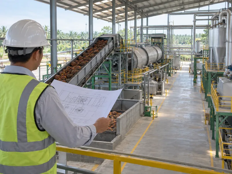
Conveyor selection should follow the actual material and transfer duty. In addition to length, the supplier needs the required lift, inlet arrangement, discharge location, and expected operating conditions. A generic conveyor description is insufficient when it must connect two fixed machines.
Identify support locations and the party responsible for each supporting structure. Check whether the arrangement crosses a walkway, vehicle route, maintenance zone, or access door. Structural loads and access requirements must be resolved by the appropriate designers rather than inferred from a product photograph.
For an existing mill, review the intended tie-in sequence. A new transfer section may require temporary removal of guards, chutes, or nearby services during installation. Plan that work as a defined shutdown activity with the responsible site team.
Reserve the Space Needed to Service Equipment
The machine footprint is only the area occupied during normal operation. Maintenance may require additional space to open covers, withdraw a shaft, lift a drive assembly, or place removed components. Ask the supplier to show the relevant service envelope on the arrangement drawing.
Review the service envelope with the maintenance team, not only with purchasing. A technically removable component may still be impractical to handle if the lifting route is blocked or the staging area is missing. These difficulties are cheaper to discover during layout review than after equipment is surrounded by permanent services.
The UK HSE maintenance guidance emphasizes planning and safe access for maintenance work. It is cited here as a design-review reference, not as a statement that UK legal requirements apply to every mill. The project team must determine the applicable local requirements and equipment-specific procedures.
Use the existing palm oil mill maintenance article to identify the kinds of equipment that will need routine attention. Then ask the actual supplier for access and removal requirements for the purchased configuration. Do not transfer a clearance from an unrelated model simply because both machines perform the same process duty.
Coordinate Utility Connections at the Equipment Boundary
Show the utility connection points on the arrangement rather than listing utilities only in a separate brochure. Steam, water, drainage, electrical supply, and any compressed-air connections need identifiable locations and owners. Their routing can affect access and the space available for future changes.
A useful interface note identifies the connection reference, required service conditions, and the limits of the machinery package. It should also state who supplies the connecting line or cable and who verifies the final installation. Avoid undefined phrases such as by others without naming the responsible project party.
The steam boiler article provides background on the mill’s steam system. Layout approval still requires coordination between the steam producer, distribution design, and consuming equipment. A suitable boiler location alone does not establish that every connected item receives the required service.
Keep drains and discharge destinations in the review. An outlet marked drain is not a complete disposal arrangement. The project’s process and environmental designers should define where each stream belongs, while the layout shows the physical route and the relevant interface boundary.
Obtain Foundation Information Before Civil Construction
Civil work should use the supplier’s confirmed foundation and loading information for the ordered equipment. General catalogue dimensions can help reserve preliminary space, but they should not be treated as a final foundation drawing. Identify which equipment dimensions remain subject to design completion.
Request the necessary support points, anchor information, and applicable operating or dynamic load data through the project’s engineering process. The civil designer must assess those inputs against actual ground and structural conditions. This article does not provide a universal foundation size because no such size suits all machines and sites.
Record drawing approvals and revisions so the civil contractor knows which version is authorized for construction. If a supplier changes an equipment connection or support arrangement, review the affected civil and utility drawings together. A small machinery change can have consequences outside the machinery package.
Make Operating Access Part of the Review
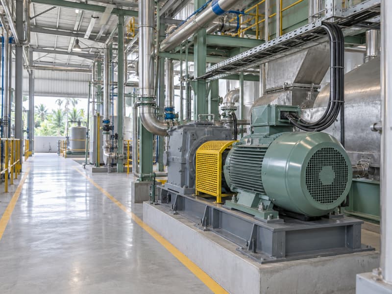
Operators need to reach the controls and observation points intended for normal operation. Check their relationship to the process rather than placing a panel wherever a wall is free. The operator should be able to carry out the tasks specified by the equipment designer using the planned access arrangement.
Review routes used for sampling, inspection, cleaning, and handling consumables. Distinguish normal tasks from work requiring a shutdown and specialized access. Where access depends on a platform or lifting provision, confirm that it is included in the relevant scope.
Avoid prescribing walkway dimensions from a general article as a substitute for a site design. The correct arrangement depends on applicable rules, personnel movement, equipment hazards, and maintenance tasks. Document the requirement and have the responsible designer resolve it.
Keep an Interface Register Alongside the Drawing
| Interface | Evidence to request | Responsible parties to identify |
| Conveyor to machine | Inlet and outlet dimensions and elevations | Both equipment suppliers |
| Machine to foundation | Approved foundation and loading information | Machinery and civil designers |
| Utility to package | Connection schedule and service conditions | Utility and package suppliers |
| Machine to maintenance route | Removal envelope and lifting requirements | Supplier and site maintenance team |
| Package to control system | Signal list and operating sequence | Package and controls engineers |
Give each interface a unique reference and a status such as confirmed, awaiting measurement, or awaiting design. Attach the relevant drawing revision and record the unresolved question. A register is useful only if the question can be assigned and closed.
Do not mark an interface complete because a drawing was received. Check that both connected parties agree with the same dimensions and conditions. If one party changes its design later, reopen the interface and assess the consequences.
Review Installation and Replacement Routes
Equipment must reach its final position before it can operate. Check transport access, unloading arrangements, doorway restrictions, and the sequence in which major items enter the building. Some installations need large machinery positioned before nearby structures or pipework close the route.
The same question returns when a component eventually needs replacement. A layout that permits initial installation through an unfinished roof may not permit later removal after the building is complete. Ask how the largest expected replacement assembly will leave the operating plant.
For press installations, discuss the actual service and handling needs while reviewing screw press equipment. The requirements belong to the selected model and its drive arrangement. Keep lifting and structural design with the competent parties responsible for those systems.
Protect Future Options with Explicit Boundaries
If expansion is planned, show the future equipment area and the interfaces reserved for it. Distinguish a genuine expansion allowance from empty space that will later be occupied by utilities or storage. Record which first-phase services are expected to support the future duty and which will need replacement.
The article on mill expansion discusses the broader decision to increase scale. A layout review should translate that intention into specific drawing requirements without assuming that every current machine can be reused. The future phase still needs its own capacity and interface assessment.
Approve the Layout with an Open-Item List
Before approval, hold a review involving operations, maintenance, civil works, utilities, and the equipment supplier. Follow the material paths and then walk through installation and maintenance tasks on the drawing. Ask each discipline to identify the interfaces it owns.
Record what is approved and what remains conditional. If a missing site measurement controls fabrication, make that dependency explicit rather than hiding it in a general comment. Approvals should point to a specific revision so the team can recognize later changes.
Send Vortech Global the latest site plan, confirmed process boundary, and interface register when discussing the equipment arrangement. The most useful review result is a coordinated set of responsibilities and dimensions. That gives the installation team a clear basis for preparing the site and connecting the purchased equipment.